A pH Measurement & Control System for the Planted Aquarium
Page 4
![]()
pH Probe Input and Amplifier

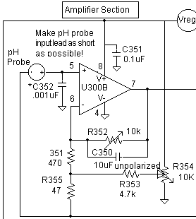
This is the only critical part of the entire circuit — the wiring from the pH electrode BNC connector to pin 5 of U300B must be as short and direct as possible. The reason for this is that this is an extremely high impedance point, and any extra wire length here will act as a very effective antenna, picking up any electrical noise in the area. If the wiring in this area is kept short, there will be no problems. In my controller, the IC butts up against the front panel BNC jack so that there is only about 1/4 inch of lead length between the BNC connector and the IC. Note that the pH probe's shield connection is not connected to the minus supply, but to the reference ground. Since the BNC jack will be electrically common with the case, this means that the case (if metal) will be at the reference ground potential as well. (A metal case is strongly recommended to help shield out interference.)
C352, combined with the probe input resistance, forms a low-pass filter at the amplifier input. It will prevent even a sizable amount of electrical noise at the input from getting into the circuit and causing trouble. (Additional components yet to be discussed also help in this regard.) The 3 dB point for this capacitor and the probe resistance is 1/(6.28*R*C), which is less than 1 Hz. The tradeoff is that the RC time constant (the product of the the capacitance and the gigaohm source resistance) is about 1 second. This means it will take a few seconds for the capacitor to charge when there's a change in pH, which will cause a noticeable settling time during calibration. If you feel you don't need C352, please feel free not to use it. If you're not sure, please include it, as it is capable of converting a very noisy input signal into a quiet one. Since this is a very high impedance part of the circuit, capacitor leakage here could be a problem. Usually, one uses low leakage (for example, polystyrene) capacitors at points like this. In practice, the garden-variety ceramic Radio Shack capacitor listed in the parts list works well, and is what is used in my controller. This ends the discussion of the circuit's only critical area. Keep the lead lengths here short and direct to prevent noise pickup and no problems should be encountered.
C351 is a simple bypass capacitor. Ideally, it should run directly between pins 4 and 8 to bypass electrical supply noise to ground. C350 is an nonpolarized electrolytic capacitor. It, like C352, is not strictly necessary, but exists to cut down the AC gain. If any 60 Hz noise gets past C352, C350 will help to keep it from being amplified to any significant extent. Again, unless you are sure you don't need it, please include it.
R352 is set to about 8500 ohms, giving a circuit gain of about 17. This is what is sometimes referred to as the "slope" adjustment in a pH circuit.
R354, R351, R355, and R353 are the offset nulling resistors. This offset array compensates for the input offset voltage of the op amp, and for the error voltage caused by the approximately 20 picoamp input current. (20 pA * 1gigaohm = 20 millivolts, which would be amplified to about 0.3 volts (0.3 pH error) if it wasn't canceled here. During calibration, R354 will be adjusted to give a reading of 7.00 when the probe is in the pH 7 calibration buffer. (Potentiometer R354 is sometimes referred to as the "Zero" adjustment in a pH circuit.) R352 and R354 are the two potentiometers that will have to be adjusted at calibration time, so make them easily accessible. (On my controller, all the 15-turn potentiometers can be reached through holes in the front panel.) Further discussion of this sort of nulling arrangement can be found in The IC Op Amp Cookbook.