A pH Measurement & Control System for the Planted Aquarium
Page 3
![]()
Detailed Discussion: Layout, Wiring, Assembly, and Operation
If you have not done so already, please print the complete schematic diagram for reference before proceeding. To simplify the circuit discussion, the schematic has been cut into five pieces for the discussion that follows.
1. Voltage Regulator and 7-volt Reference Ground
2. pH Probe Input and Amplifier
3. Inverter and pH Display
4. Comparator
5. Valve ActuatorVoltage Regulator and 7-volt Ground Reference

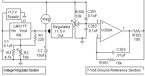
The 12-volt DC power supply listed in the parts list is not voltage-regulated, so the first task is to put its output through a LM317 IC voltage regulator. The unloaded output of the specified supply is about 15 volts. This voltage drops under load (to about 13.5 volts at half its rated 500mA load), but setting the LM317 regulator's output to 11.5 volts allows it plenty of head room. This 11.5 "Vreg" regulated voltage will let the op amp outputs get up to about 10.6 volts. (It is this 10.6 volt maximum output voltage from the op amp outputs that limits the pH range that can this circuit can measure). The 4.7k resistor R3, in parallel with the 15-turn trimmer R2, makes it easier to set the regulated voltage to the exact value.
This section of the schematic diagram also shows the 7-volt reference ground section. As was noted in the overview, this design uses a cheap, readily available single voltage supply. Since this supply doesn't have the usual ground, plus, and minus voltages used in most op amp circuits, a "reference ground" must be generated. Reference grounds are usually set to one half the supply voltage, so you might expect the reference ground voltage here to be set at 5.75 volts (11.5 / 2 = 5.75). But as was mentioned in the overview, the reference ground here has been set to 7.00 volts, so a zero input from the probe (neutral pH, pH 7.00) gives an output voltage of 7.00 volts.
R300 is simply a voltage divider used to set the reference ground level. Its output is buffered by a unity gain op amp, U300A. The 100 ohm resistor, R302, promotes circuit stability by isolating the op amp output from load circuit capacitance (including the considerable capacitance of the pH probe cable to which it is connected). The output voltage is fed back to the op amp inverting input via R301. AC gain is cut by feedback capacitor C303. C301 and C302 bypass noise. (Further discussion of generating reference grounds in this way can be found in the Horowitz and Hill's The Art of Electronics.)