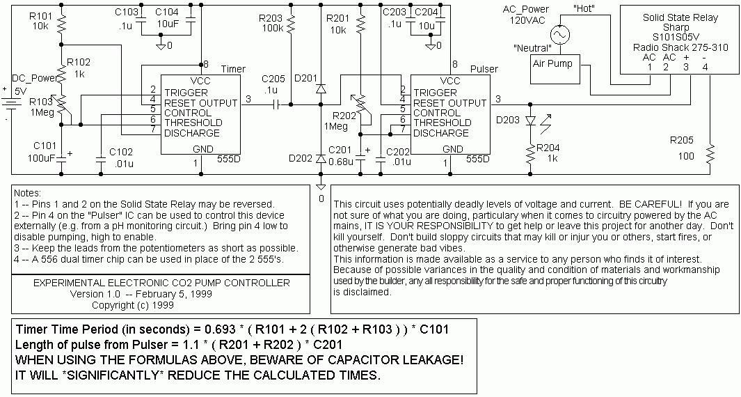
Circuit Explanation

The first 555 IC, "Timer", is configured as an astable multivibrator--essentially an electronic clock. Its output (pin 3) drops from High (nominally 5 volts) to Low (ground), with a time period determined by the equation given above (every 200 seconds with the values shown).The second 555 IC, "Pulser", is configured as a monostable multivibrator -- a pulse generator.
The Timer's output (pin 3) is coupled to the pulser's input (pin 2) via C205, which works as an differentiating signal conditioner (i.e. it converts a pulse that is seconds long into a short, sharp triggering spike that is more to the 555's liking). R203 holds the pulser input high when there is no trigger signal. Diodes 201 and 202 work as "snubbers" to keep the pulser's trigger input from being driven over 5 volts or below ground by the trigger signal.
Once triggered, the pulser puts out a pulse at pin 3, the length of which is determined by the equation given above (3/4 second with the values shown). This positive pulse lights two light emitting diodes (LEDs): D203, the "Pump On" indicator diode, and the LED within the Solid State Relay. (Using an LED to internally optically couple the low voltage firing signal to the relay's Triacs, which control the 120 VAC, provides "optical isolation" of the high voltage part of the circuit from the 5 volt "logic" part. TAKE CARE TO KEEP PINS 1 & 2 OF THE RELAY WELL INSULATED/ISOLATED FROM PINS 3 & 4, (AND THE REST OF THE LOGIC CIRCUITRY) LEST YOU COMPROMISE THIS ISOLATION. It takes a lot of current to light the relay's internal LED enough to fire the triacs in the relay reliably, so R205 is of fairly low resistance (100 ohms, to give about 40mA).
The air pump is connected so that its connection to the "hot" side of the AC line is via the solid state relay. For added safety, a second relay could be triggered in parallel with the first to control the AC "neutral" connection as well. The 555 is capable of sourcing more than enough current to drive this second device.